Let's begin:
Step 1.0
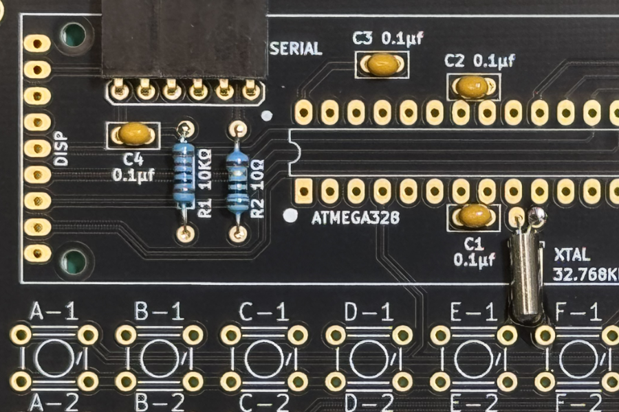
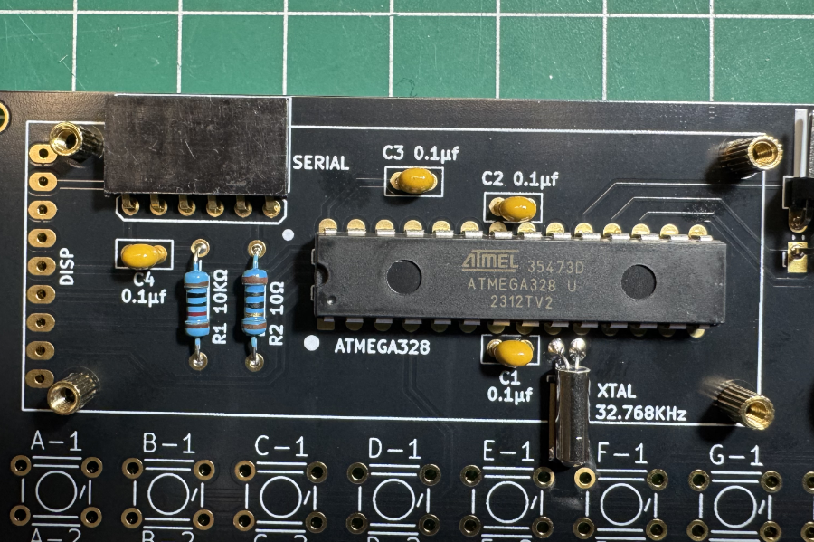
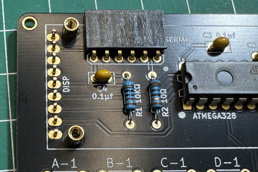
Start by soldering the shortest components.
- Resistors R1 and R2
- Capacitors C1, C2, C3 and C4
- Serial header
- 32.768KH Crystal XTAL
It is good practice to solder the crystal can to the PCB.
Step 2.0
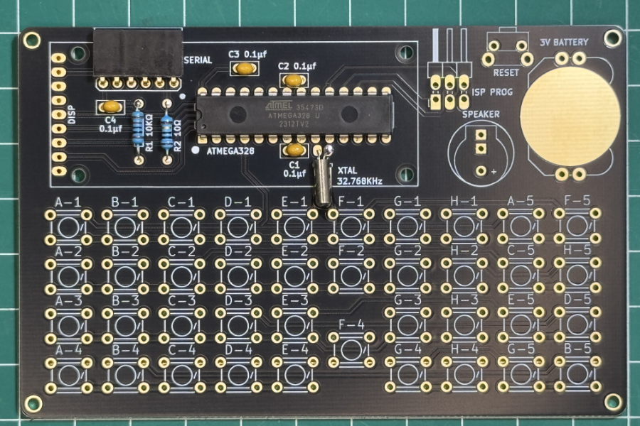
- Set the microcontroller completely flush against the board.
- Make sure the microcontroller notch or dot (pin 1) is aligned with the pcb markings.
Step 3.0
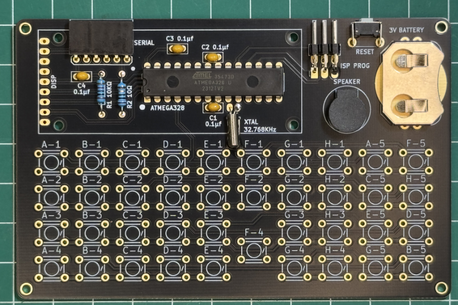
Continue to solder:
- CR2032 Battery holder.
- Rest switch.
- ISP Programming header
- Speaker
Step 4.0
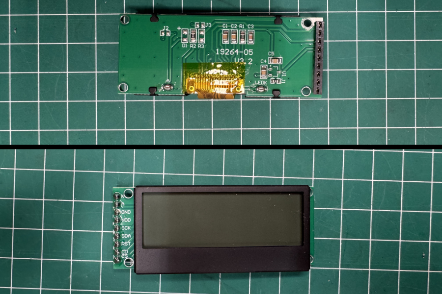
- Solder the 9-pin female header onto the display module.
Step 5.0
- Mount the four 4mm brass spacers using 3mm bolts.
Step 6.0
Mount the display header.- Insert the 9 pin male header from the bottom.
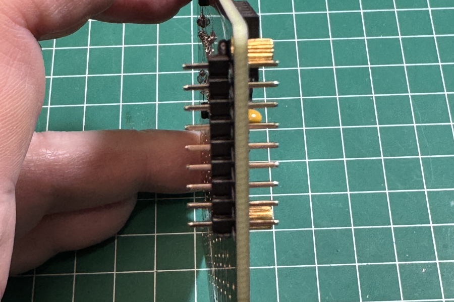
- From the front side of the PCB push the pcb so that the pins protrude more.
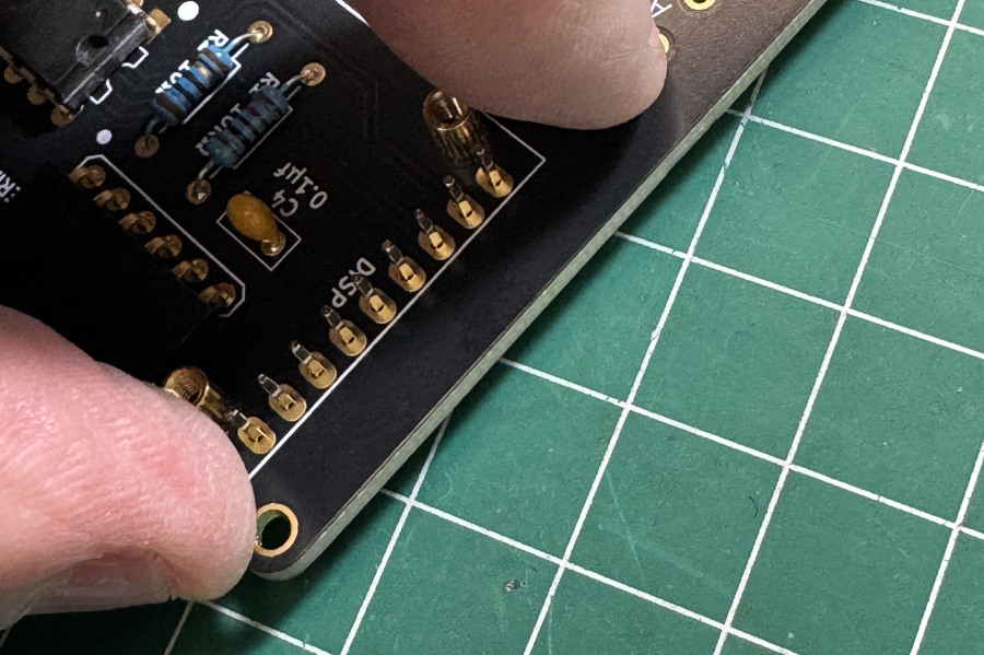
- Mount the display module with the 3mm bolts and insert the header.
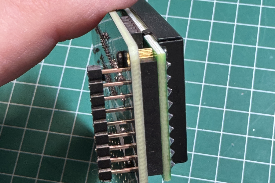
- Solder the 9 pin header.
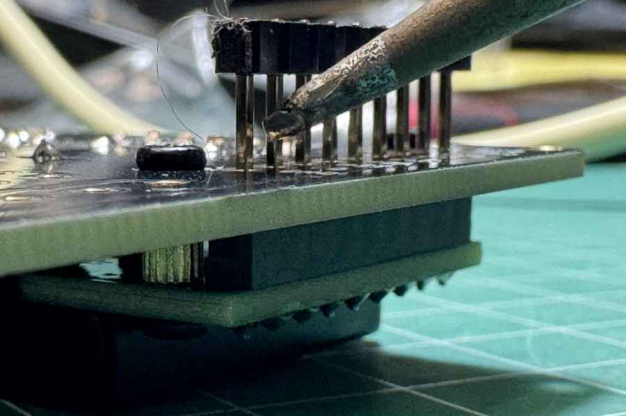
- Remove the plastic holder from the 9 pin header and cut the leads short.
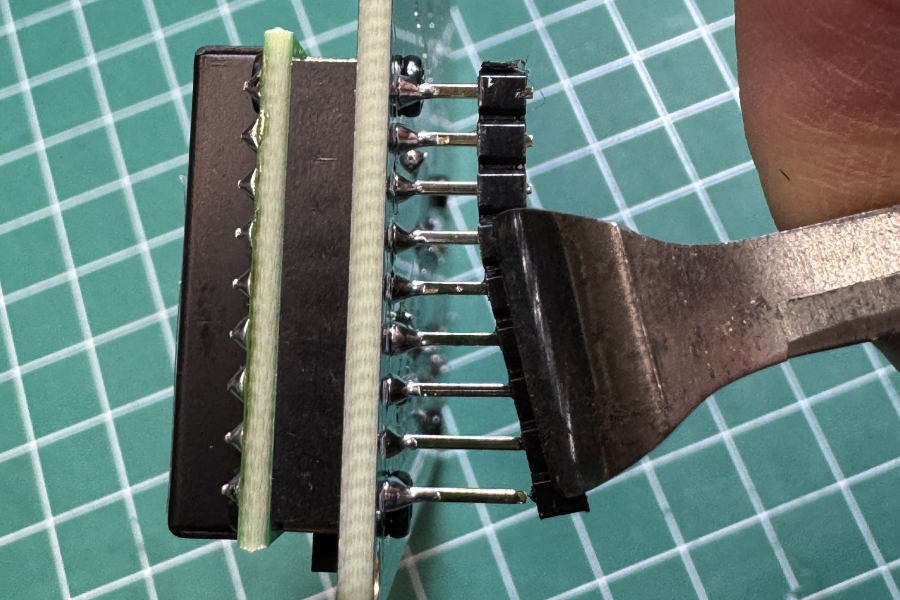
- Remove the display module.
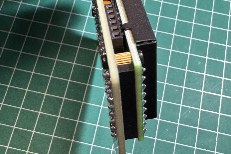
- This is how it should look.
Step 7.0
Adding the 39 buttons.- Take the 3d printed case and flip is over.
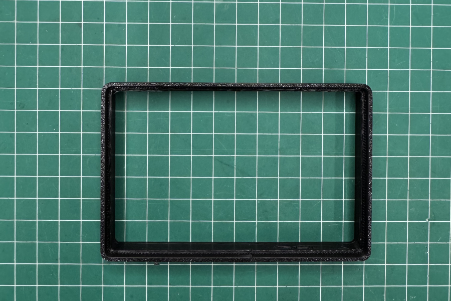
- Place the PCB on the back side of the 3d printed case.
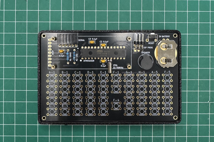
- Mount all 39 buttons.
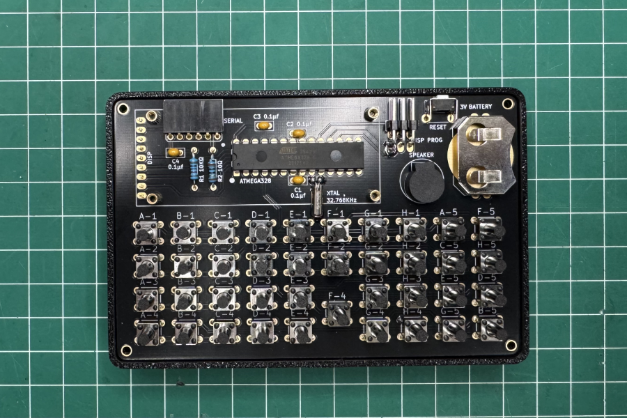
- Attach the 7mm brass posts with the 5mm bolts to the top plate.
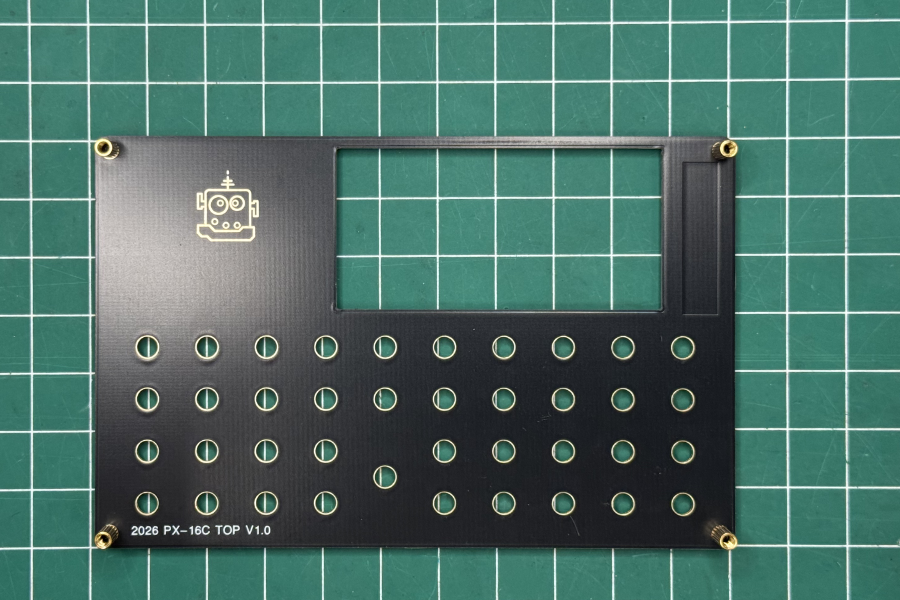
- Place the top cover to help align the buttons.
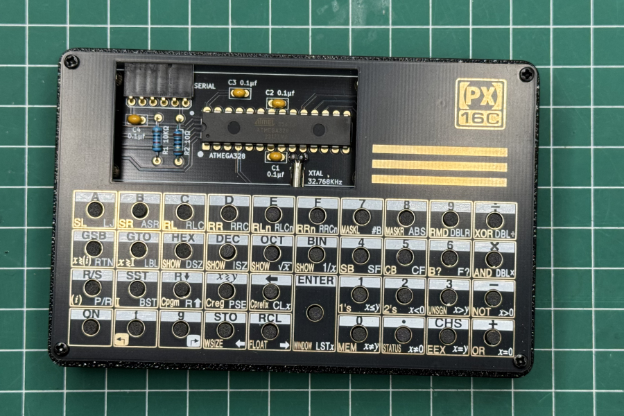
- Remove the 3D-printed case and flip the PCB to solder all the buttons. Keep the top panel in place to prevent the buttons from shifting. Start by soldering only two diagonal pins on each button. Verify that all buttons are properly aligned, then proceed to solder the remaining pins.
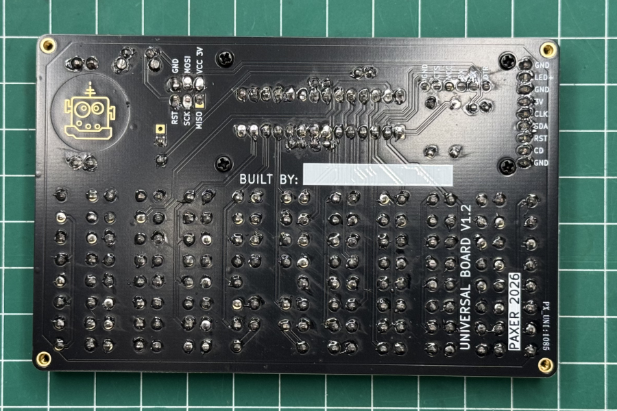
Step 7.0
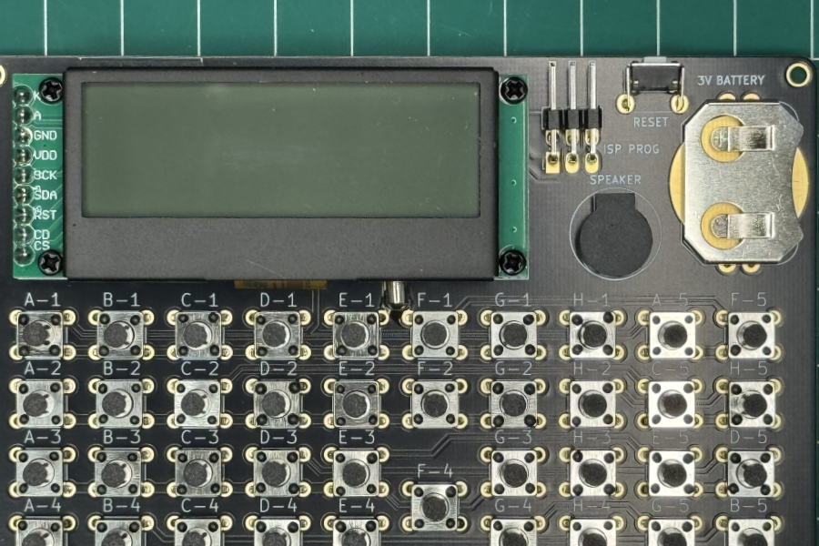
Mount display module.- Mount the display moudle using the four 3mm bolts.
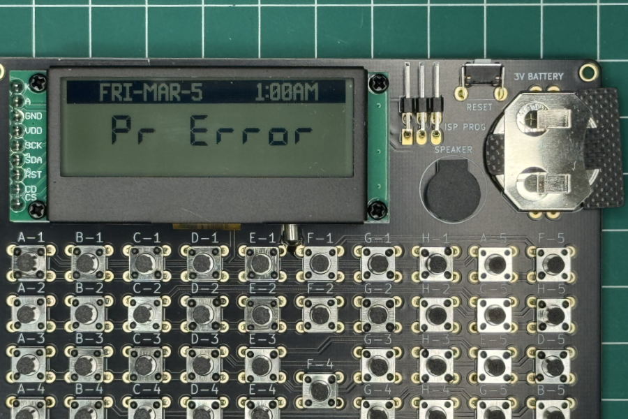
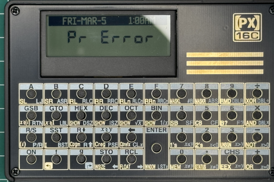
- Now it's time to test the calculator. Insert a 3V CR2032 coin battery and the display should show "Pr Error".
Step 9.0
Assemble the 3D case.- Take the 3d printed case and place the bottom panel on the back.
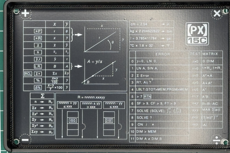
- Place the PCB on the top of the case.
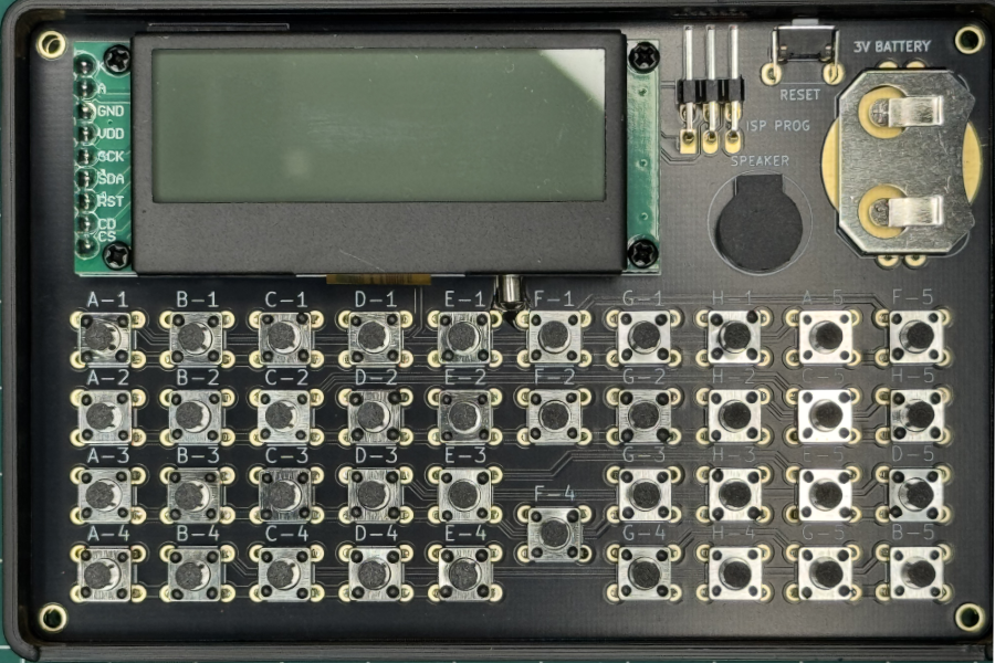
- Place the top panel with the 7mm brass bolts on top.
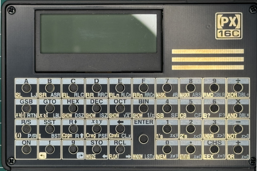
- Flip the calculator and screw the bottom plate with the 8mm bolts.
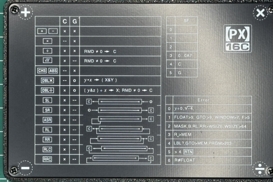
- This is how it should look.
Schematic
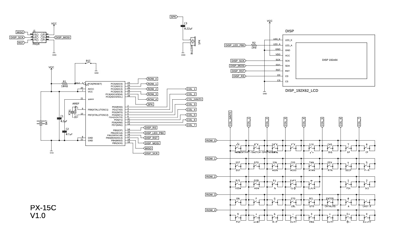
Part List
| Part | Value | Description |
|---|---|---|
| C1, C2 | 0.1µf | Decoupling Capacitor |
| C3 | 0.1µf | Speaker impedance |
| U1 | ATMEGA328P | Microcontroller |
| J1 | 6 pin female headers | PI Programing header |
| BAT | Battery Holder | CR2032 Battery Holder |
| SPK | BUZZER | Speaker |
| XTAL | Clock Crystal 32.768kHz | Clock |
| R1 | 10KΩ | Reset pullup resistor |
| R2 | 10Ω | LCD backlight resistor |
| BTN's | 6x6mm tactile switch 7mm height | Key buttons |
| RST | 6x3.5 mm tactile button | Reset button |
| DISP | Display 192X64 LCD | Display |